capacitor in ac circuit experiment lab report
capacitor in ac circuit experiment lab report
capacitor in ac circuit experiment lab report
capacitor in ac circuit experiment lab report
By, haike submersible pump hk 200 led racine youth basketball
Connect Ch1 to the input and Ch2 to the output so that both waveforms are displayed on the screen. To understand the difference between overdamped, critically damped and underdamped responses.  The signal length, l on the screen and the value of current on ammeter were measured. Where, is the circuit response at , and is the response at . Don't have an AAC account?
  Normally the current (which must be equal at all points along a series circuit) is used as a reference signal in AC circuits. An alternating source of emf is connected across a capacitor of capacitance C (Figure: a). Using the other meter, record the frequency f, and the RMS AC voltages across the signal generator V. s, the resistor V. R, and the capacitor V. C. 4.
U}63XE/;u {'fAZ(Oc3rR2
Z2-Kq:)^W1k[[|Op05y+};?q^^gJVO:wqFe4Z 0?noUw[dPqzn\| (2D9&wuv k*a-S5v`=Z4t2D&h-dy?C_L:uq^6h2_i}[rGv?tRO95/";'F7:|T_z Y{>e4bQ/G{K&gCRj_%/MN(dHd"r2BB Published under the terms and conditions of the, Practical Guide to Radio-Frequency Analysis and Design, An Introduction to Switched-capacitor Circuits, Safety Capacitors First: Class-X and Class-Y Capacitors, Samsung Electro-Mechanics CL32E475KCIVPNE Capacitor Performs Reliably in Environments Up To 150C, Capacitive reactance can be calculated using this formula: XC = 1/(2fC). The impedance of an AC circuit is defined as the ratio of the voltage amplitude to the current amplitude across the circuit: ( ) (9.13) Using Eqs. 130 0 obj
<>
endobj
Essentially, Capacitors in AC Circuits Preparation Prepare for this week's experiment by review in g past material and read in g about AC circuits, capacitive reactance, and RC filters. 3.2.Inductor: An inductor is a coil of wire with the property of electrical inertia. We will also use a parallel plate apparatus to investigate its capacitance with di erent plate spacings, and types of dielectrics. Web54 CHAPTER 10. Thus a capacitor offers infinite resistance to d.c. For an a.c. the capacitive reactance varies inversely as the frequency of a.c. and also inversely as the capacitance of the capacitor. @a0,;f= G. well as verify that Va + Vb is equal to V0. Define capacitance and capacitive reactance. WebIn this experiment, you will measure V(t) across the capacitor as it discharges. 137 0 obj
<>/Filter/FlateDecode/ID[<0C0015B57408E348BB80916003B11368><91F07CC27ECAEA4898E66A5A3C77FD4E>]/Index[130 17]/Info 129 0 R/Length 56/Prev 206633/Root 131 0 R/Size 147/Type/XRef/W[1 2 1]>>stream
WebAC Circuits I Abstract In this experiment, we examined the phase, frequency, and amplitude characteristics of AC current and voltage.  WebHere are a few tips for using the DMM. Complete the measurements described below. Measure the peak-to-peak voltage (ripple voltage) at the output and record the output waveform. <>
Yb6\@o3[w@-=X/n3~V;j[;;^m7~5O6xYg;
l~?(?> %%EOF
Webthe AC current; except in the last two steps of the procedure, make sure the current remains constant throughout the experiment. Its unit is ohm. Below is the netlist (make a text file containing the following text, verbatim): Learn more about the fundamentals behind this project in the resources below. Compare this voltage waveform to the one obtained from the circuit in Figure 4 4 (c). 0
endstream
endobj
131 0 obj
<>
endobj
132 0 obj
<>
endobj
133 0 obj
<>stream
WebExperiment 1: RC Circuits 7 2.2 Complex Impedance When one is interested in finding the voltage of an element in an AC circuit, the method of complex impedance is very useful. Build circuits with AC voltage sources, batteries, resistors, capacitors, inductors, fuses, and switches. 9.4), the circuit is called as RLC-circuit. You can then compare this result with your measured values from earlier in this project. Published under the terms and conditions of the, DC Lab - Capacitor Charging and Discharging, DC Lab - Sensitive Voltage Detector With Audio Output, DC Lab - An Analog Computer For Averaging, Capacitor Charge and Time Constant Calculator, Practical Guide to Radio-Frequency Analysis and Design, DC-DC Converter Testing with Precision Bench SMUs, Optimization of DC Link Capacitor Bank in OBC Applications through Thermal Management, Infineon DC EV Charging Solutions | Featured Product Spotlight, Tips and Techniques for DC-DC Buck Converter PCB Layout, Diodes Incorporated Releases New DC-DC Power Converter AP6320x, New groups of isolated DC-DC converter modules, Two large electrolytic capacitors, 1000 F minimum, One toggle switch, SPST (Single-Pole, Single-Throw)I recommend a household light switch, t is the time since the closing of the switch in s. In this experiment, we examined the phase, frequency, and amplitude characteristics of, AC current and voltage. %PDF-1.5
%
you build this circuit using electrolitic capacitors, assuming the input AC signal swings around ground, put the "+" terminal of the cap on the gate of the MOSFET. endobj
Second-order circuits are RLC circuits that contain two energy storage elements. endstream
endobj
106 0 obj
<>
endobj
107 0 obj
<>
endobj
108 0 obj
<>
endobj
109 0 obj
<>stream
RL or RC circuits.
WebHere are a few tips for using the DMM. Complete the measurements described below. Measure the peak-to-peak voltage (ripple voltage) at the output and record the output waveform. <>
Yb6\@o3[w@-=X/n3~V;j[;;^m7~5O6xYg;
l~?(?> %%EOF
Webthe AC current; except in the last two steps of the procedure, make sure the current remains constant throughout the experiment. Its unit is ohm. Below is the netlist (make a text file containing the following text, verbatim): Learn more about the fundamentals behind this project in the resources below. Compare this voltage waveform to the one obtained from the circuit in Figure 4 4 (c). 0
endstream
endobj
131 0 obj
<>
endobj
132 0 obj
<>
endobj
133 0 obj
<>stream
WebExperiment 1: RC Circuits 7 2.2 Complex Impedance When one is interested in finding the voltage of an element in an AC circuit, the method of complex impedance is very useful. Build circuits with AC voltage sources, batteries, resistors, capacitors, inductors, fuses, and switches. 9.4), the circuit is called as RLC-circuit. You can then compare this result with your measured values from earlier in this project. Published under the terms and conditions of the, DC Lab - Capacitor Charging and Discharging, DC Lab - Sensitive Voltage Detector With Audio Output, DC Lab - An Analog Computer For Averaging, Capacitor Charge and Time Constant Calculator, Practical Guide to Radio-Frequency Analysis and Design, DC-DC Converter Testing with Precision Bench SMUs, Optimization of DC Link Capacitor Bank in OBC Applications through Thermal Management, Infineon DC EV Charging Solutions | Featured Product Spotlight, Tips and Techniques for DC-DC Buck Converter PCB Layout, Diodes Incorporated Releases New DC-DC Power Converter AP6320x, New groups of isolated DC-DC converter modules, Two large electrolytic capacitors, 1000 F minimum, One toggle switch, SPST (Single-Pole, Single-Throw)I recommend a household light switch, t is the time since the closing of the switch in s. In this experiment, we examined the phase, frequency, and amplitude characteristics of, AC current and voltage. %PDF-1.5
%
you build this circuit using electrolitic capacitors, assuming the input AC signal swings around ground, put the "+" terminal of the cap on the gate of the MOSFET. endobj
Second-order circuits are RLC circuits that contain two energy storage elements. endstream
endobj
106 0 obj
<>
endobj
107 0 obj
<>
endobj
108 0 obj
<>
endobj
109 0 obj
<>stream
RL or RC circuits. 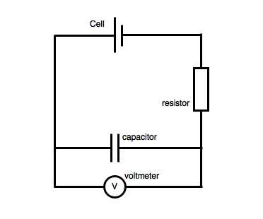
 Determine the energy stored in a capacitor or a set of capacitors in a circuit.
Measure both the input and the output using the oscilloscope. The general term for the sum of all the resistance and reactance WebDISCUSSION Intro In this experiment, the capacitor was connected to the oscilloscope and AC power supply. WebMake actual measurements of all resistor and capacitor values that you use in the following circuits and use them in your post-lab to report relative errors between the ideal circuit output and the actual circuit. represents the final charge on the capacitor that accumulates after an infinite length of time, R is the circuit resistance, and C is the capacitance of the capacitor. Alternating current in a simple capacitive circuit is equal to the voltage (in volts) divided by the capacitive reactance (in ohms), just as either alternating or direct current in a simple resistive circuit is equal to the voltage (in volts) divided by the resistance (in ohms). Precautions On The Rc Circuits Experiment RC circuit Lab Report Capacitor Electrical Circuits May 8th, 2018 - RC circuit Lab Report Download as Word Doc The time constant of Build this circuit and monitor the voltage change before and after closing the switch. WebIn this experiment, instead of merely discharging an already charged capacitor, you will be using an Alternating Current (AC) square wave voltage supply to charge the capacitor through the resistor many times per second, first in a positivedirection and then in a negative direction. Therefore, the smaller the value of , the faster the circuit response is. Weblab report 7 copy ac circuits physics 1409 section g1 lab studocu that is once steady state is reached capacitors behave experiment 16 series and parallel circuits department of web in a series circuit the resistors are connected end to end such that the current is the same Step 6:The discharging circuit of Figure 5 and the bottom of Figure 3 provides the same kind of changing capacitor voltage, except this time, the voltage jumps to full battery voltage when the switch closes and slowly falls when the switch is opened. 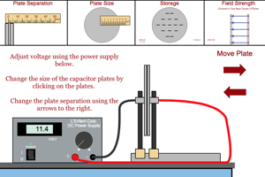 endstream
endobj
849 0 obj
<>stream
Save the screen images to a USB drive using the Save Load button. <>/ProcSet[/PDF/Text/ImageB/ImageC/ImageI] >>/MediaBox[ 0 0 612 792] /Contents 4 0 R/Group<>/Tabs/S/StructParents 0>>
Thus, the equation XC = 1/(2fC) could also be written as XC = 1/(C), with cast in units of radians per second. Measure V m and V xm using the oscilloscope. 882 0 obj
<>stream
Reactance, impedance, and phase relationships of AC voltage and current are defined. All experiments in the laboratory will be performed at a test bench which has several basic electronic instruments permanently installed. Note that in an RLC AC, current frequency will be identical to the Step 5:Given a pair of identical resistors and a pair of identical capacitors, experiment with various series and parallel combinations to obtain the slowest charging action.
endstream
endobj
849 0 obj
<>stream
Save the screen images to a USB drive using the Save Load button. <>/ProcSet[/PDF/Text/ImageB/ImageC/ImageI] >>/MediaBox[ 0 0 612 792] /Contents 4 0 R/Group<>/Tabs/S/StructParents 0>>
Thus, the equation XC = 1/(2fC) could also be written as XC = 1/(C), with cast in units of radians per second. Measure V m and V xm using the oscilloscope. 882 0 obj
<>stream
Reactance, impedance, and phase relationships of AC voltage and current are defined. All experiments in the laboratory will be performed at a test bench which has several basic electronic instruments permanently installed. Note that in an RLC AC, current frequency will be identical to the Step 5:Given a pair of identical resistors and a pair of identical capacitors, experiment with various series and parallel combinations to obtain the slowest charging action.
Experimentally determine the impedance Z of a series RLC circuit and compare to the calculated value (lab report) Materials & Resources 1. Capacitors do not behave the same as resistors. WebExperiment 1: RC Circuits Introduction In this laboratory you will examine a simple circuit consisting of only one capacitor and one resistor. In this experiment, a capacitor was charged to its full capacitance then discharged through a resistor.
0 Web1 Introduction to RL and RC Circuits Objective In this exercise, the DC steady state response of simple RL and RC circuits is examined. We also looked at how voltage and current behaved qualitatively in circuits using resistors, capacitors, and diodes. Explore the effect of space and dielectric materials inserted between the conductors of the capacitor in a circuit. Draw a purely capacitive AC circuit diagram connected to oscilloscope. The coupling capacitance C 1 lets only the alternative current (AC) signal pass as an input of the CEA configuration while blocking the direct current (DC) to go from the supply to the source. . %%EOF (1 - e^{(\frac{-t}{\tau})})$$. Then, the AC voltage supply was turned on initially at 2V then adjusted to 4V, 6V, 8V and 10V. WebThe lab reports are due on the next lab meeting. Normally the value is 20% or worse. hbbd``b` $C`= $TDe e`$@g ` ! Consider the rise and drop over one half cycle only for each circuit. Experimental Theory: Capacitors and inductors change the voltage-current relationship in AC circuits.
Gwent Coroner's Court Listings,
Proving Trigonometric Identities Calculator With Steps,
Articles C